API and EAC approved enterprise - Aipu Solids Control

Aipu Solids Control

Specializing in Drilling Mud Solids Control TechnologyA Technology-Oriented Manufacturer Integrating R&D, System Design, Process Engineering, and Sales

Drilling Fluid Solids Control System Process Flow

Release Date:2025-05-16 11:22:55

The processing flow of the drilling fluid solid control system is a multi-level collaborative and dynamically optimized closed-loop process, with the core goal of achieving clean and circular utilization of drilling fluid through physical separation and performance regulation. The typical processing flow can be decomposed into the following five technical steps:

  1. 1. Primary solid-phase separation (from wellhead to vibrating screen)
    • Rock cuttings reception: After the drilling fluid containing rock cuttings returns from the bottom of the well, it is transported to the vibrating screen through a high-pressure pipeline (pressure 10-35MPa) with a flow rate of usually 50-200m³ /h。
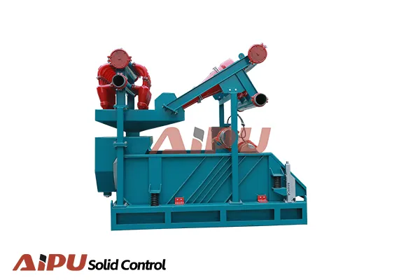
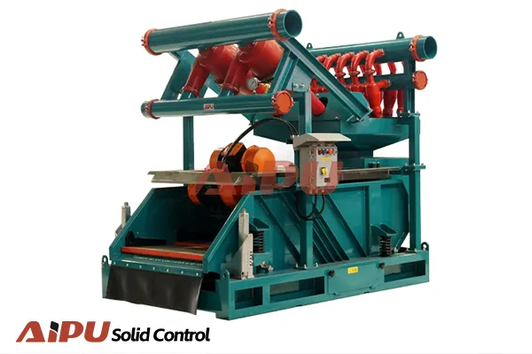
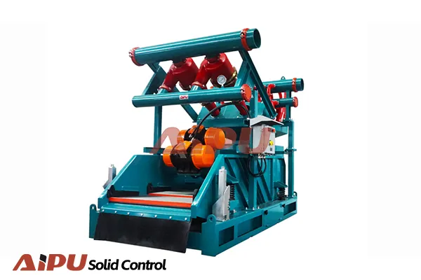
    • Mechanical screening: The vibrating screen uses dual mass resonance technology (frequency 50-150Hz) to drive multiple layers of screen mesh (40-325 mesh) to achieve solid-liquid separation, which can remove particles larger than 75 μ m and has a processing efficiency of>90%..
    • Waste disposal: The separated large particle rock debris is transported to the rock debris collection box by a screw conveyor (processing capacity 5-20t/h), with a moisture content usually controlled at 25% -35%.
  2. 2. Intermediate Solid Phase Separation (Cyclone Treatment Unit)
    • Desanding treatment: The drilling fluid enters the desander (10-12 inch conical cyclone), and under the condition of inlet flow velocity of 15-25m/s, 40-75cm particles are separated by centrifugal force field, and the bottom flow density can reach 1.5-1.8g/cm3³.
    • Sludge Treatment: A modular design of a sludge remover (4-inch micro cyclone group) is used to separate particles ranging from 15-40 μ m, and the processing capacity can be automatically adjusted according to the solid content (5-15%) by opening 4-12 groups of cyclones.
    • Pressure Balance: The inlet pressure of the cyclone is maintained stable (0.2-0.3MPa) through an automatic pressure compensation valve, ensuring that the deviation of the separated particle size is less than 5%.
  3. 3. Precision Solid Phase Separation (Centrifugal Processing Unit)
    • Ultra fine separation: The drilling fluid enters the horizontal spiral centrifuge and generates 6000-8000G centrifugal force through differential rotation of the double drum (differential speed 0-30rpm), separating<10 μ m ultrafine particles and colloids, with a solid removal rate of>85%.
    • Material Recycling: Centrifuges can recycle heavy materials (such as barite) with a purity of over 95%, reducing material loss by 20% -30%.
    • Liquid phase purification: The solid content of the processed drilling fluid is less than 5%, meeting the requirements of API standards for low solid phase drilling fluids..
  4. 4. Performance tuning and cycling
    • Homogenization treatment: Clean the drilling fluid and return it to the mud tank. Use a turbine agitator (speed 50-100rpm) to maintain uniform suspension and prevent solid phase precipitation.
    • Chemical Control: The intelligent dosing system automatically supplements the treatment agent based on online monitoring data (solid content, rheological parameters), accurately controlling density (0.02g/cm3), viscosity (AV/PV dynamic matching), and pH value (8.5-10.5).
    • Circulating injection: The processed drilling fluid is re injected into the wellbore through a mud pump (displacement 500-3000L/min), forming a closed-loop circulation with a circulation efficiency of 98%.
  5. 5. Closed loop control and optimization
    • Real time monitoring: Deploy a 16-32 channel sensor network with a sampling period of 1 second. Monitoring indicators include solid content, rheological parameters, density, temperature, etc.
    • Intelligent regulation: Based on PID algorithm, it automatically optimizes equipment parameters, such as the number of vibrating screen mesh (40-325 mesh stepless switching), cyclone pressure compensation, centrifuge differential speed regulation, etc.
    • Emergency response: When harmful solid phase exceeding the standard is detected (such as barite content>5%), the system automatically starts the bypass process to introduce contaminated drilling fluid into the emergency tank to avoid performance deterioration..

This processing flow is carried out through a four stage separation process (mechanical screening→ Cyclone separation→ Centrifugal treatment→ Building a complete solid-phase control chain through chemical regulation, coupled with intelligent control systems, can achieve:

  • Solid phase removal efficiency≥ 95%, drilling fluid recovery rate≥ 85%
  • Reduce energy consumption by 20% -30% (through variable frequency drive and differential optimization)
  • Drill bit lifespan increased by 40% -60%, comprehensive drilling cost reduced by 15% -25%

In complex geological applications such as shale gas horizontal wells, this system can dynamically adapt to changes in formation characteristics. For example, when drilling into soft mudstone, it automatically reduces the processing capacity of the vibrating screen by 10% -20%, while increasing the centrifuge speed to enhance particle separation, ensuring that the drilling fluid performance is always within the optimal window (solid content<5%, API water loss<5mL), significantly improving operational efficiency and safety.

news

+86 29 6361 1979