Designing an efficient solids control layout is fundamental to the success and safety of any modern drilling operation. A well-planned system directly impacts drilling performance, fluid costs, and environmental compliance. The primary goal is to create a logical and compact flow path for drilling fluid, allowing for the step-by-step removal of drilled solids of varying sizes. This process is critical for maintaining the desired properties of the drilling mud, which in turn protects the wellbore, enhances the rate of penetration, and minimizes waste volumes. A poor layout, conversely, leads to equipment inefficiency, increased chemical consumption, and higher operational costs. The key is to integrate individual pieces of equipment into a cohesive, high-performance system.
The Core Principles of an Efficient Layout
An effective design is built on several core principles. First is the concept of a gravity-fed flow. The equipment should be arranged to allow drilling fluid to move through the various stages of solids removal primarily by gravity, minimizing the need for transfer pumps which can shear the fluid and degrade its properties. Second, the layout must be compact to reduce the overall footprint, but not so cramped that it hinders safe access for operation and maintenance. Third, the system must be designed for redundancy and flexibility, allowing for the bypass of specific equipment for maintenance or to handle different drilling conditions without shutting down the entire process.
Sequential Equipment Placement and Flow
The arrangement of equipment follows the logical progression of solids removal, starting with the largest cuttings. The flow typically begins at the shale shakers, which are the primary and most critical solids removal devices. They should be the first equipment to receive fluid from the flow line. The screen undersize from the shakers then flows directly into the degasser, if needed, to remove entrained gases. Following this, the fluid should be routed to the desander, a hydrocyclone that removes fine sand-sized particles. The desander underflow is then fed into the desilter, which uses smaller hydrocyclones to remove even finer silt-sized solids. Finally, a centrifuge can be employed as a final polishing step to remove ultra-fine particles and recover valuable barite.
Practical Considerations for Implementation
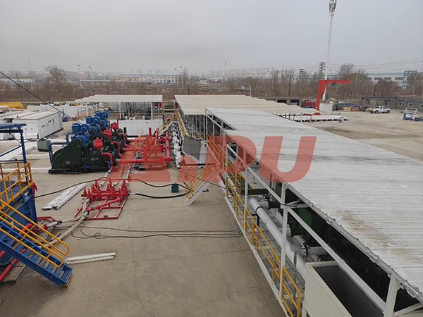
Beyond the theoretical flow, practical considerations are paramount. Ensure there is sufficient space around each unit for daily inspections, screen changes, and parts replacement. All walkways and platforms must be safe and non-slip. The sump and tank design is also crucial; they should be baffled properly to prevent short-circuiting and allow for adequate settling and treatment time. The suction and discharge lines must be correctly sized to prevent bottlenecks and ensure smooth fluid handling. Planning for these details during the design phase prevents costly modifications and downtime later in the field.
For companies seeking reliable and high-performance solids control equipment to integrate into their layout, Aipu offers a comprehensive range of solutions. With a strong reputation for durability and efficiency, Aipu's shale shakers, desanders, desilters, and centrifuges are engineered to work seamlessly together, providing a robust foundation for building an efficient and cost-effective solids control system.